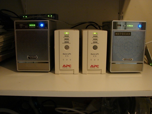
I have two ReadyNAS NV+ units from Netgear and I’ve put them in a backroom where nobody normally goes. I don’t either. Now, for extra security in case of fire or a break-in, I’m actually moving them to a neighbor’s spare room, which means I can’t easily get at them anymore and the energy consumption could become a problem. As could the constant whining, but I don’t think so.
The problem with the ReadyNAS is that even though you can power them down through their config pages using a browser, there is no way to switch them on again short of actually, physically, walking over there and pressing the blue button. There’s no wake-on-lan or any other similar provision. The only alternative is to have it power on and off according to a schedule, which is what I have done so far. But if you do that, that schedule will be unnecessarily liberal, just in case you need access to the units. I’m mainly using them for Retrospect backups and disk images when doing recovery, and very little else, so I don’t even use them every day. I calculated that the 16 hours a day these two boxes are running, costs me around 900 kWh per year. That’s around $150 in electricity per year. And it’s ecologically rude, too.
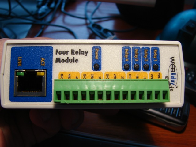
So, I got me a little unit from Control by Web. The unit is called WebRelay and you can get it in several different versions. The version I ordered has four outputs and is powered by 5V or PoE (hoping I’ll ever get a switch with PoE, that looked like a good idea). This thing actually has a built-in web server that let’s you configure and use it.
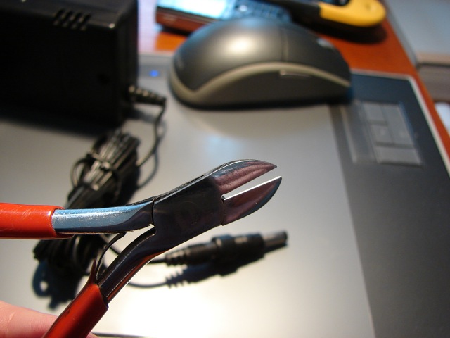
I also ordered a separate power supply from an unrelated brand, so I had to cut off the plug and just screw down the bare leads.
Now that I had the WebRelay powered up, I could configure it from a browser (see the downloadable user manual for details). It’s done using a little arp and a little browser work. That’s it. Very easy. The end result is that you can switch on, switch off, or pulse, any of the four outputs over the lan or the internet.
Time to modify the ReadyNAS boxes. Time to give you a straight warning, too.
I’m only describing what I did, not recommending you do the same. By opening up the box like this you definitely void any warranty you may have. You have a fair chance of destroying the unit, electrocuting yourself, and setting fire to your house. Your wife may divorce you for making burn holes in the curtains or setting the house on fire. Your dog may bite you. Your parents may disinherit you. So, don’t do it. Unless you know what you’re doing, and if so, you wouldn’t be reading this anyway, you’d just do it.
So, that being said, let’s prepare the unit for slaughter. First of all, make four labels for the discs. Strangely, the disc carriages have no identification on the front, so they’re easy to mix up when putting back and I can’t imagine that would do your RAID volumes much good.
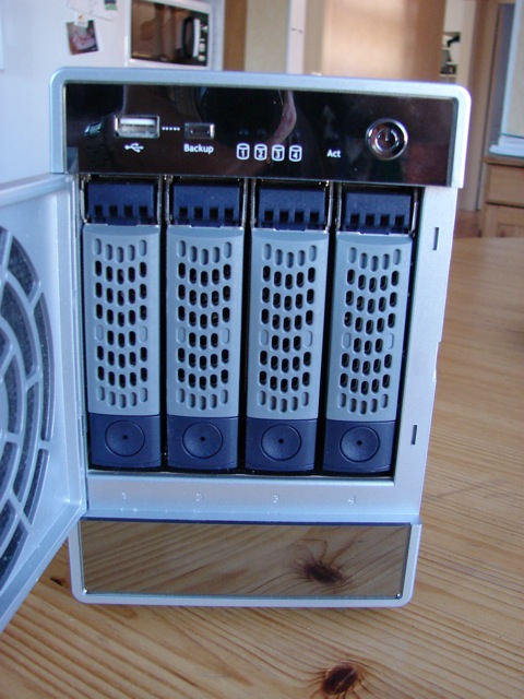
This is what the discs should look like, properly labeled:
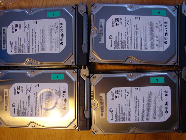
Now, put those aside in some safe spot.
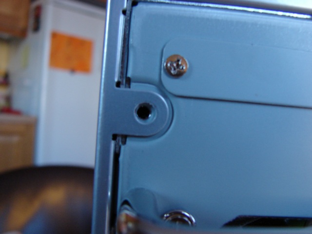
Remove the four screws from the back panel on the ReadyNAS:
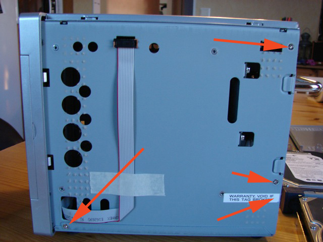
Take off both side panels. On the left side (seen from the back) you have to unplug the flatcable connector close to the top. (It connects the display to the motherboard.) Remove the four screws, including the one under the warranty label (you did read my disclaimer above, didn’t you?).
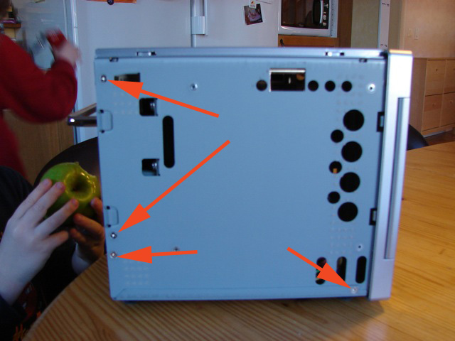
The right side also has four screws which you should remove while fending off any four-year-olds that try to stuff half-eaten apples into the unit:
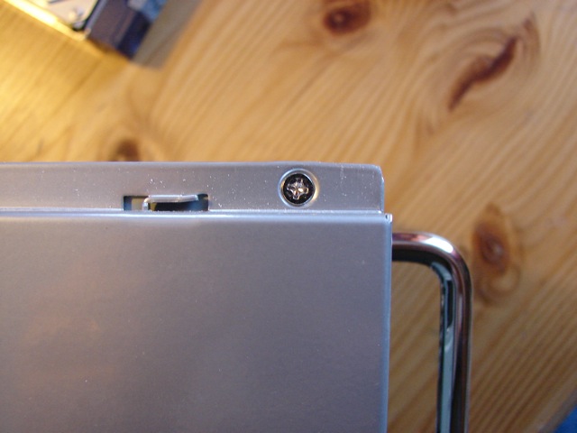
Remove the four screws from the top panel:
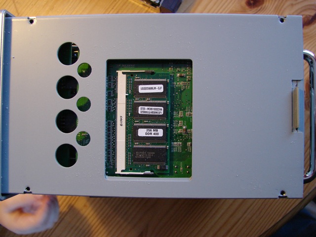
And this is the access opening for adding RAM, by the way:
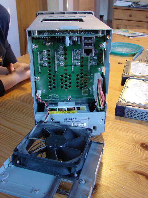
The back panel with the main connector and the big fan now comes off easily. Disconnect the fan feed at the bottom left in the picture and put the whole thing aside:
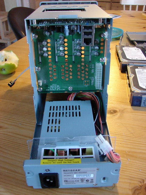
Next, disconnect the huge Molex power connector on the right side and slide out the power supply. Put it aside as well:
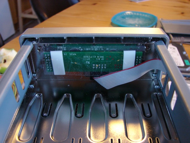
Just for kicks, behind the power supply, up agains the front panel, is a board with the LCD display on it (the unit is upside down in this shot):
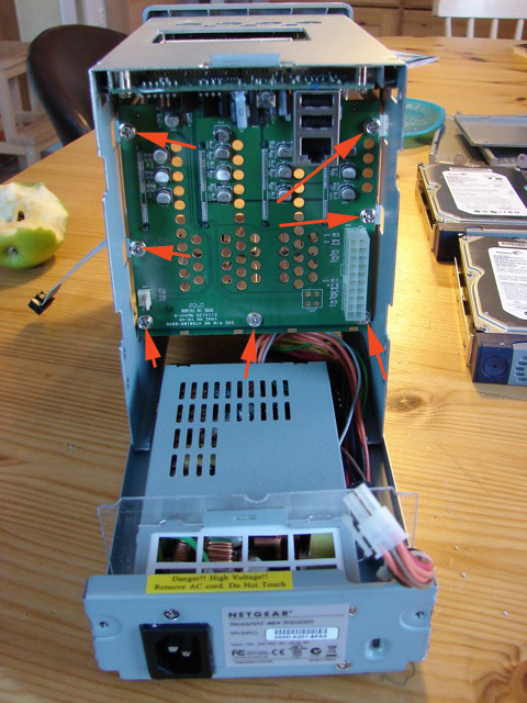
Now, take out the seven screws that hold the SATA backplane in place. So far all the screws were of the same kind, but these are different, so keep track of which is which:
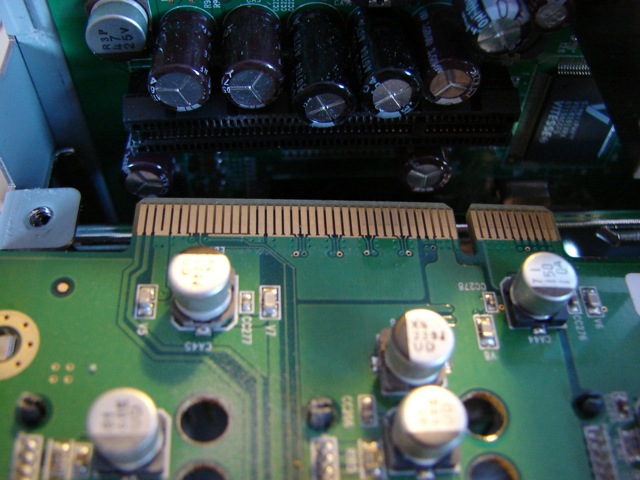
Now you can easily unplug the SATA backplane and slide it out:
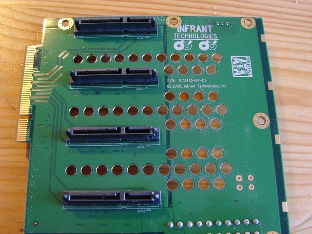
Turning it over, you’ll see the SATA connectors:
Next, we’ll slide out the entire motherboard (the unit is face down in this shot):
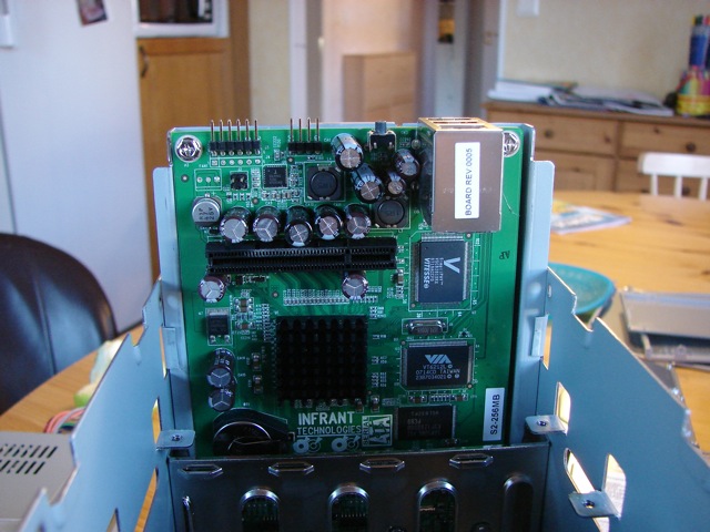
And you’ll notice that the motherboard and the frontpanel LEDs and switches board are together on a single carrier of steel:
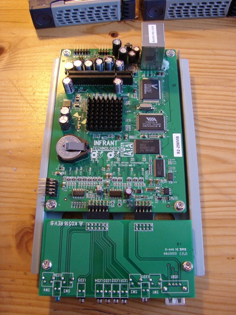
If you look carefully, you’ll see a little bit too many switches here. Netgear simply put in two switches behind each of the front panel buttons. If you line up the board with the front panel it becomes obvious:
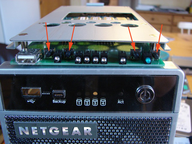
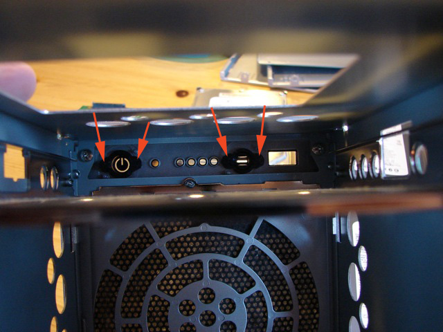
Taking a peek into the box, you can see that the two frontpanel buttons (“backup” and “on/off”) are wide enough to press both their respective buttons at the same time:
Beeping out the wiring with a Fluke 77 (from the ’80s), it becomes clear that the switches are in parallel, as one would expect (a sight of relief, actually, since if there had been some other arrangement, I would have been up the proverbial creek here):
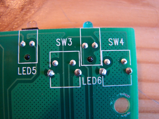
This makes a terrific amount of sense, actually. Not only will the front panel buttons be nicely balanced, but you have built-in redundancy that is bound to prolong the useful life of the unit considerably. I imagine those switches to be the weak point is the system, so having them doubled is great.
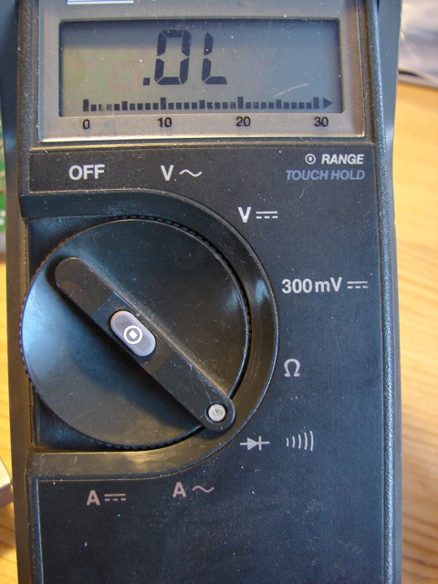
To beep out the traces, you need a multimeter with a beep function that won’t blow out your circuits if you misapply it. A regular ohmmeter may deceive you since it gives much too little load, and a battery and beeper may overload the circuits. On the Fluke, this is the setting:
Following the paths and confirming by beeping with the Fluke, we find that these two pins on the connector are connected together when pressing the on/off button:
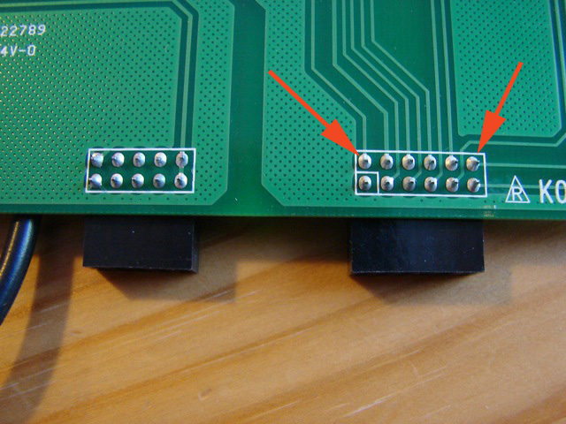
You can see in the images that I took out the front panel board from the carrier, but you don’t need to do that at all. You can get at all the places as is.
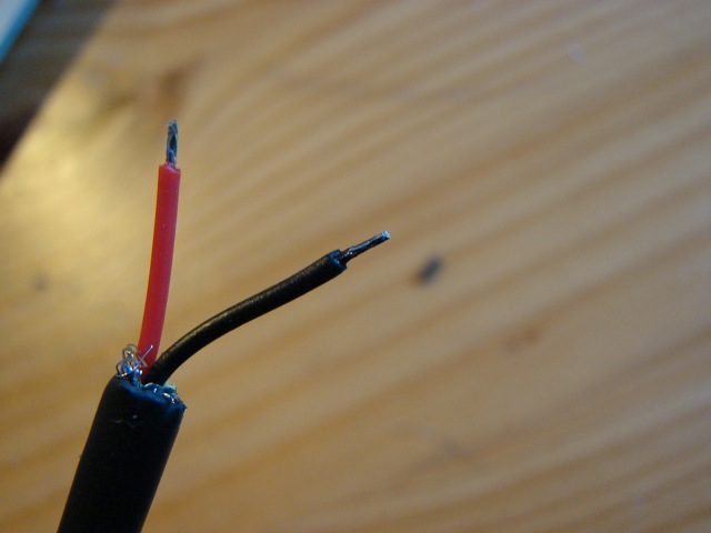
Take a piece of wire and strip it out like in the picture. I chose microphone wire. It should have been a dual lead, each 0.2 mm2, but the store delivered a quad lead. No matter. I cut the extra two leads off very short as well as the screen. Add a bit of solder to the leads:
We need to tie down the cable to the board somehow and I chose to use the connector leads on the motherboard side for that. I wrapped a small tie around one of the legs. Don’t wrap it around multiple legs, since you may push them together if you pull too hard on the tie.
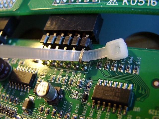
And then I tied down the cable: (don’t forget to trim down the tie)
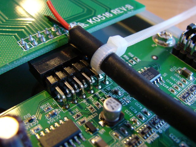
Finally, solder down the two leads to the right pins on the connector (doesn’t matter which lead goes to which pin, it’s symmetrical):
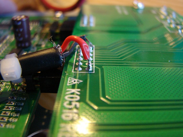
Cut the cable to about this length, so it sticks out a bit beyond the end of the motherboard:
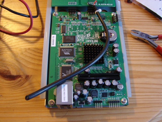
Now comes the time to the chassis connector. I chose a 3.5 mm stereo phone plug. Don’t use mono! None of the two leads we use should be connected to the chassis of the ReadyNAS, so we have to have a stereo plug and use only the tip and the distal ring.
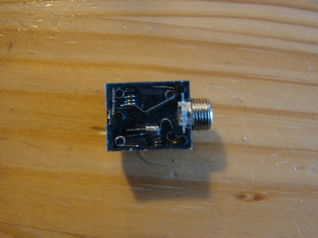
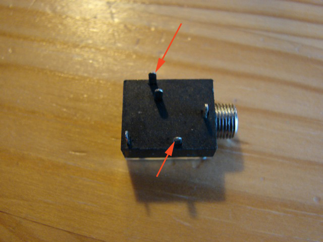
Flipping it over we can identify the two tabs we need to use:
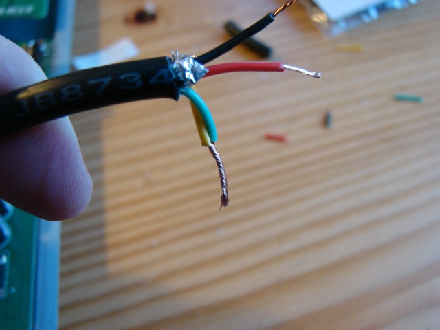
So, let’s strip the cable at this end. This time I cut the shield short, but saved the two unused leads as an anchor.
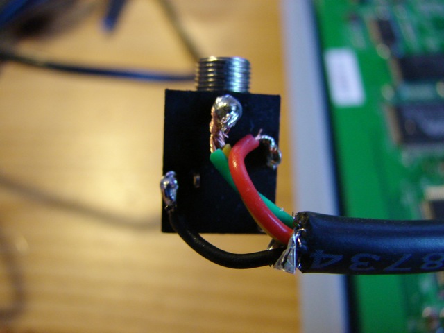
I’ll solder those to the tab that connects the chassis, that is the tab closest to the threaded cylinder to the right in the image above. That way, the cable is well anchored. Give a little extra slack to the other two leads, solder all of them carefully:
Slide the motherboard and front panel board on their carrier back into the case, while letting the cable with the chassis connector dangle on the outside:
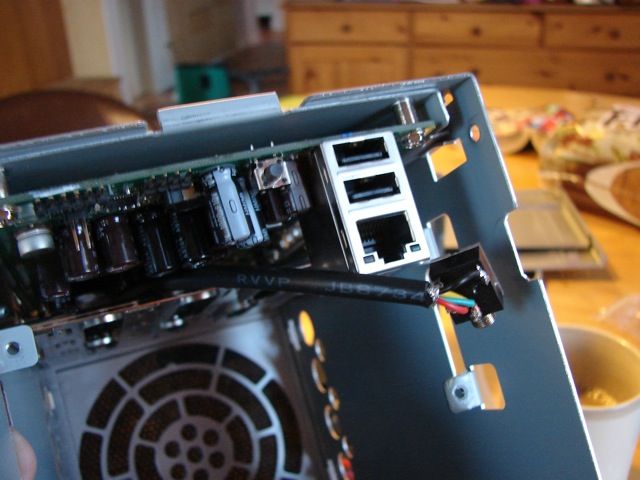
Take care to place the cable to the side of the backplane connector. There’s no lack of space, really:
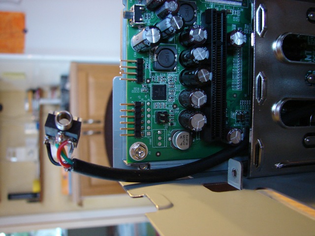
Then slide in the backplane and put back the seven screws that holds it to the chassis:
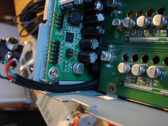
Slide in the power supply and connect the big white Molex:
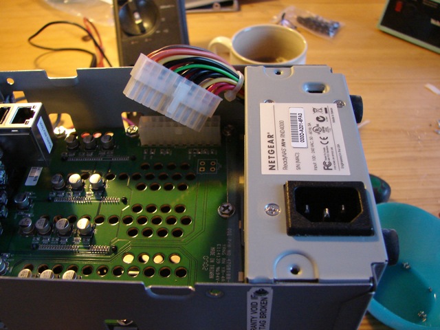
Reconnect the LCD display cable to the motherboard (the unit is face down in this shot):
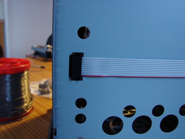
It’s time for drilling a hole in the backpanel for our connector. Find a drill bit that is just a tiny size larger than the threaded part of your chassis connector, then drill for king and country.

Except, think a bit first about the exact spot, so that you won’t conflict with components on the motherboard. Don’t rush into it, or you’ll end up with a back panel looking like a swiss cheese. After drilling, bring the back panel close enough so you can put in the new connector and don’t forget to reconnect the fan:
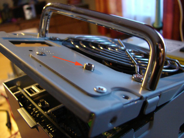
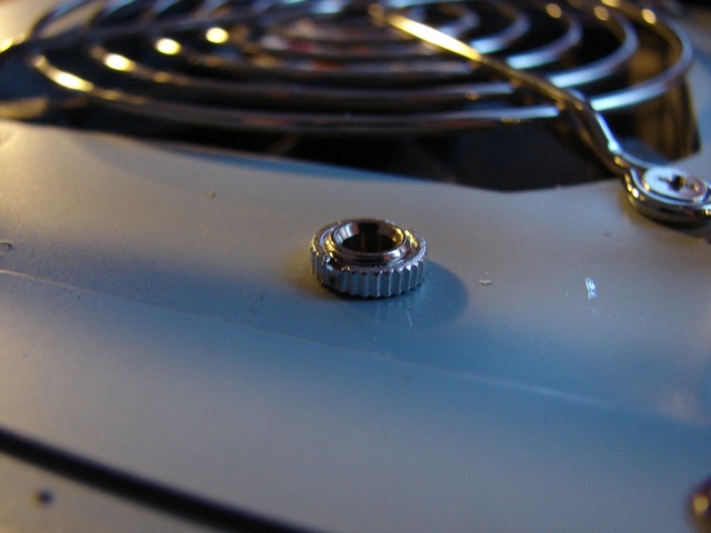
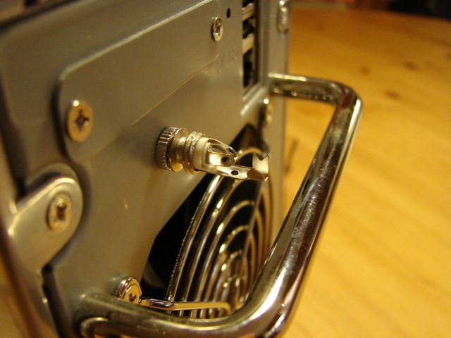
Anchor the connector with the threaded ring that comes with the connector, and tighten it well, but don’t go wild:
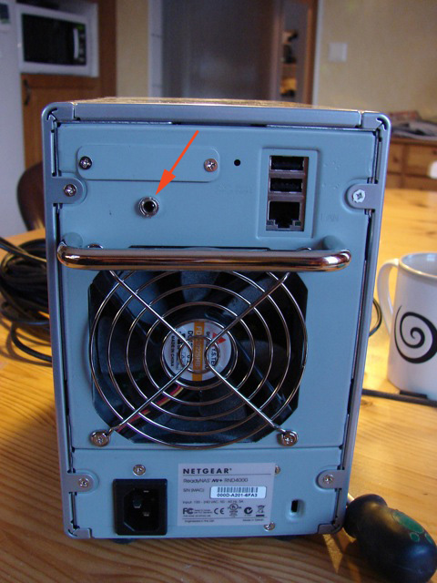
This is the right spot to drill that hole (I hope you read this far before starting to drill…):
Let’s make the external cable. Don’t make it too long, since it’s not impossible it will work as an antenna and bring in external electrical noise into the system. Make it just long enough and have the shield connected at the ReadyNAS end (see below):
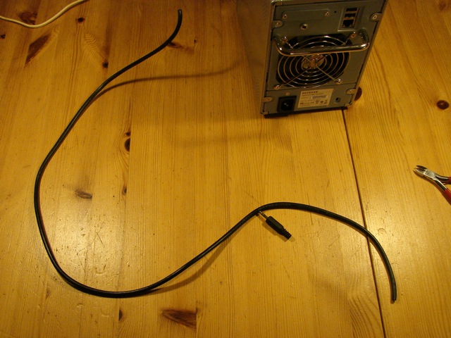
Screw apart the plug and slide the housing over the cable (it’s so shameful to discover you forgot after soldering on the connector, but in this case you can get it on from the other end, of course):
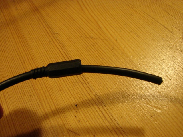
Strip the cable, preserving the shield this time, but cutting off the two extra leads (if you have those) and make the remaining leads about this long:
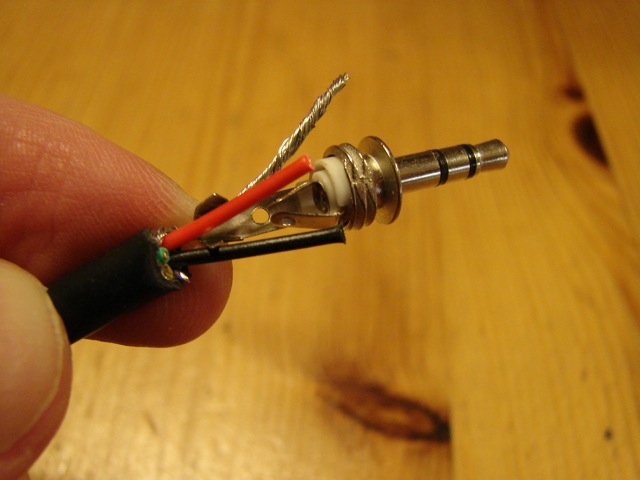
It’s best if you have some kind of clamp to hold on to the plug while soldering, but sticking it into the chassis connector works if you don’t:
Solder the shield to the long, outer ring connection and the two active leads to the tip and middle ring, like so:
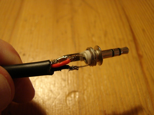
If you have teflon crimp tubing, you could have used that to protect the solder joints, but I don’t have any. Or can’t find it, at least.
For clarification, it’s the tip and the distal ring that are connected to the active leads and to the front panel switch:
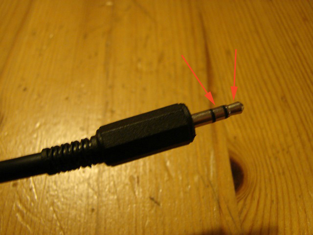
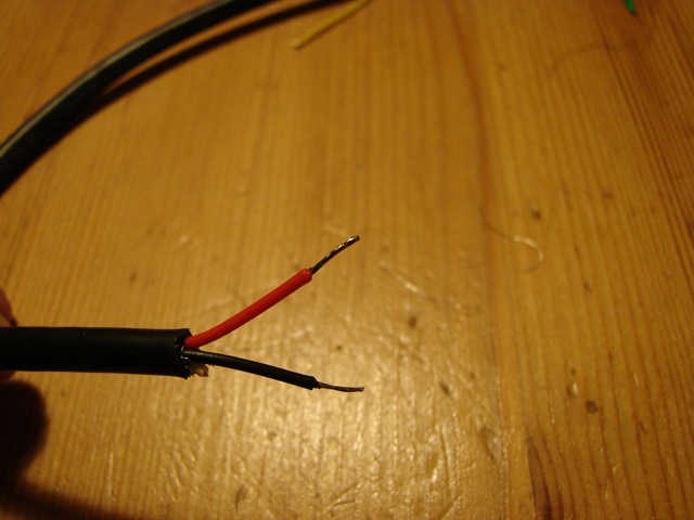
The other end of the external cable should simply be stripped to the two active leads. Cut the other leads and the screen short. If you feel like it, solder the ends so they won’t fray (not a good idea for higher amperage leads like for house lighting, but quite ok for low voltage electronics):
And connect them to the first relay in the WebRelay unit. Note that you have to connect to the “C” (Common) terminal and to the “NO” (Normally Open) terminal. Not to the “NC” (Normally Closed) under any circumstances!. (If you do, you’ll have the same effect as if you pressed the power button on the ReadyNAS forever without ever letting go. Diagnostics… reset… etc, etc…)
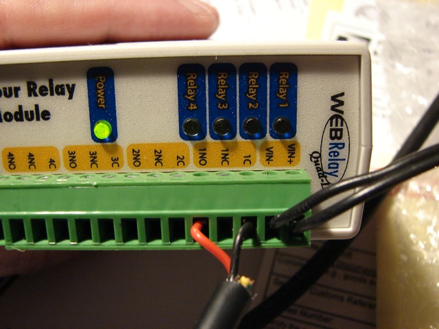
Connect the WebRelay to the local net:
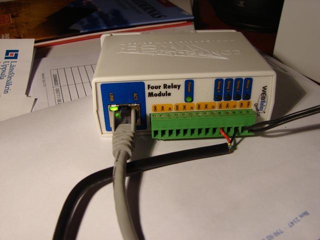
Follow the WebRelay user manual to give it an IP number, then configure it via the browser interface (read up on it yourself). Then finally, cross your fingers, click “Pulse” in the web interface (I set it to a 1.5 second pulse) and watch the ReadyNAS start…
…or blow up, or whatever. Mine started. Yihaa!!!
So now I can start this ReadyNAS from anywhere in the house, or even from anywhere on the internet if I open a port in the main router (which I didn’t). I can shut it down using the regular ReadyNAS web interface. I’m a very happy person and tomorrow I’ll do the other unit.

This is a little more than I want to take on. However, it is very very well written with clear and detailed pictures!
If you are not a technical writer, you ought to be!
Thanks,
Matt
Wow… nice setup.
I didn’t know about the ‘web relay’ thing… it seems like many many of my devices could be setup that way. I have a home-made Windows Home Server that I HATE leaving in all the time, and with 6 drives it is a real power hog… since it uses a regular tower case, I am definitely going to see about just putting a remote switch in parallel with the case switch… same thing with my main PC to which I have to remote desktop sometimes.
Re: Awake,
You don’t have to go through all that to power on a PC remotely. Investigate the ‘Wake-on-LAN’ feature.
Excellent Article, Martin!
Great to have you as a member of the ReadyNAS community. Keep up the good work!
@ArgusX: http://tinyurl.com/ReadyNAS-WOL
I had the problem of wanting to run a daily sync between one ReadyNas NV+ over the street in the neighbours house and the one in the office building.
I programmed the external NAS to power up at 7 and power down at 7:30 every weekday.
Then I added an rsync job to sync the two NAS.
I found, that as along as rsync is running, the external ReadyNAS will not power down, until the job is finished.
So if there’s a long backup job, it will take as long as it takes. Otherwise, the external ReadyNAS will power down after 30 minutes.
I’d recommend using an internal sub-miniature relay. Connect it’s NO contacts in parallel to the Power-On switch. The relays’ power (5V) comes from outside. So this has two advantages: You can use thousands of feets of controlling cable, because the acting circuit remains inside. The controlling circuit comes from outside and has *no* connections to whatever inside’s circuits!!!
Alternatively you can use an opto-coupler, with no mechanical parts!
Dan
That’s indeed a good tip, Dan. The only problem may be where to get the power. You could take it from the power supply to the web relay which, if you selected the right model, is 5V. But if you power your webrelay from a PoE source, you don’t have that. You could also steal power from inside the ReadyNAS. Must be a lot of places you can take 5V in there. But on the whole, I admit it would have been better to use an internal relay or opto coupler. It wouldn’t add much to the cost or the effort and reduce the risk to the equipment considerably.
How much power does the web relay use?
I seem to remember less than 1 W, but I can’t swear to it.
Just thinking out loud; would it be possible to do the connections via the 20 pin molex power connector instead?
Usually you can get an ATX power supply to turn on by connecting the green wire (pin 14) to any of the blacks (e.g. pin 15 right next to it).
Looks a lot less intrusive to me, and based on your picture the green wire is there, so with the above listed disclaimer (fire, divorce, financial ruin and dog bites), that may be worth a try?
You’re probably right. Next time I do something like this, I’ll check the specs for the power supply first and if it has one of those “turn me on” lines, I’ll go for that. Actually, I should’ve beeped out the line further. Wouldn’t surprise me if that on-switch actually connects to the green line, but I’m just guessing.
This is great but I prefer to use a $5 mini servo/solenoid to press the on-off button mechanically. That way I would keep my unit untouched and would not void the warranty.
Hi
to not void the warranty and build a cheap circuit I built this http://dl.dropbox.com/u/32942046/RemoteFingher/WoL-RemoteFinger.htm using the WakeUP On LAN function on a standalone ethernet NIC and an linear actuator found in a car-wrecker.
Ciao
Michele
This is a very nice walkthrough. I used it when I got my ReadyNas NV+ some time back, and I’ve just done it again with my ReadyNas 104, which is even simpler as the power supply is external. Both work like a charm and I can even turn the servers on with an IR remote I’ve connected to the relays. Sweet.
Anyways; Thanks for taking the time to do this document!