
I have the Razer Mako speakers on my desk. They consist of this heavy, huge amplifier/bass unit and two smaller round treble speakers. It’s a great sounding system, but a lot of them fall victim to the “click of death”. This is a failure mode where the speakers give a regular clicking or popping sound, about once a second, and no other sound comes out of them. As the system warms up, the popping disappears and they function fine again. Until the next time you switch them off and the misery starts over.
With these symptoms, I was pretty sure there must be a failed electrolyte capacitor in the power supply somewhere. The problem is knowing which one. Searching on the net after schematics for the Mako, I found a lengthy and interesting thread about this on the Australian Whirlpool forum (go figure…) where the solution is described very well. Someone, somewhere, figured out which capacitor fails, which makes the repair quite simple.
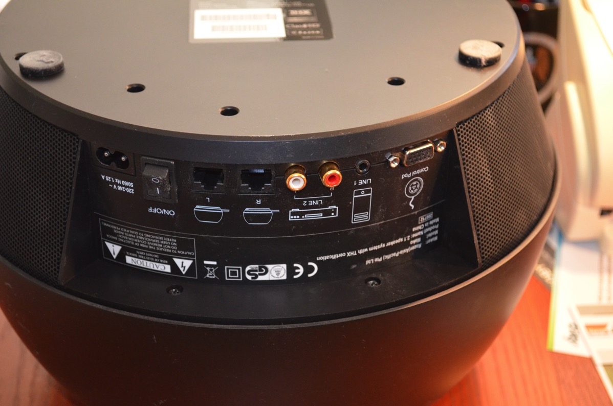
So, here’s what I did, in pictures. Disconnect the base unit from power, satellite speakers and the control pad.

Turn it over. You’ll find 11 (I think) screws in the bottom plate. Remove them all. There’s one in the middle hidden by the label, you have to remember to remove that one, too.
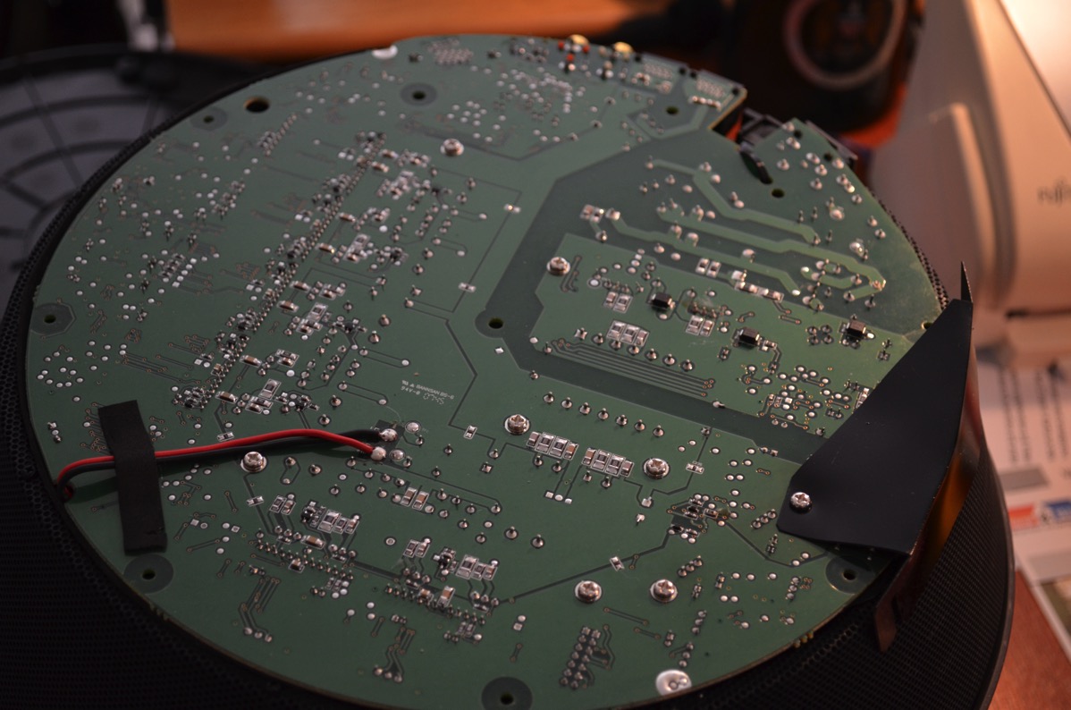
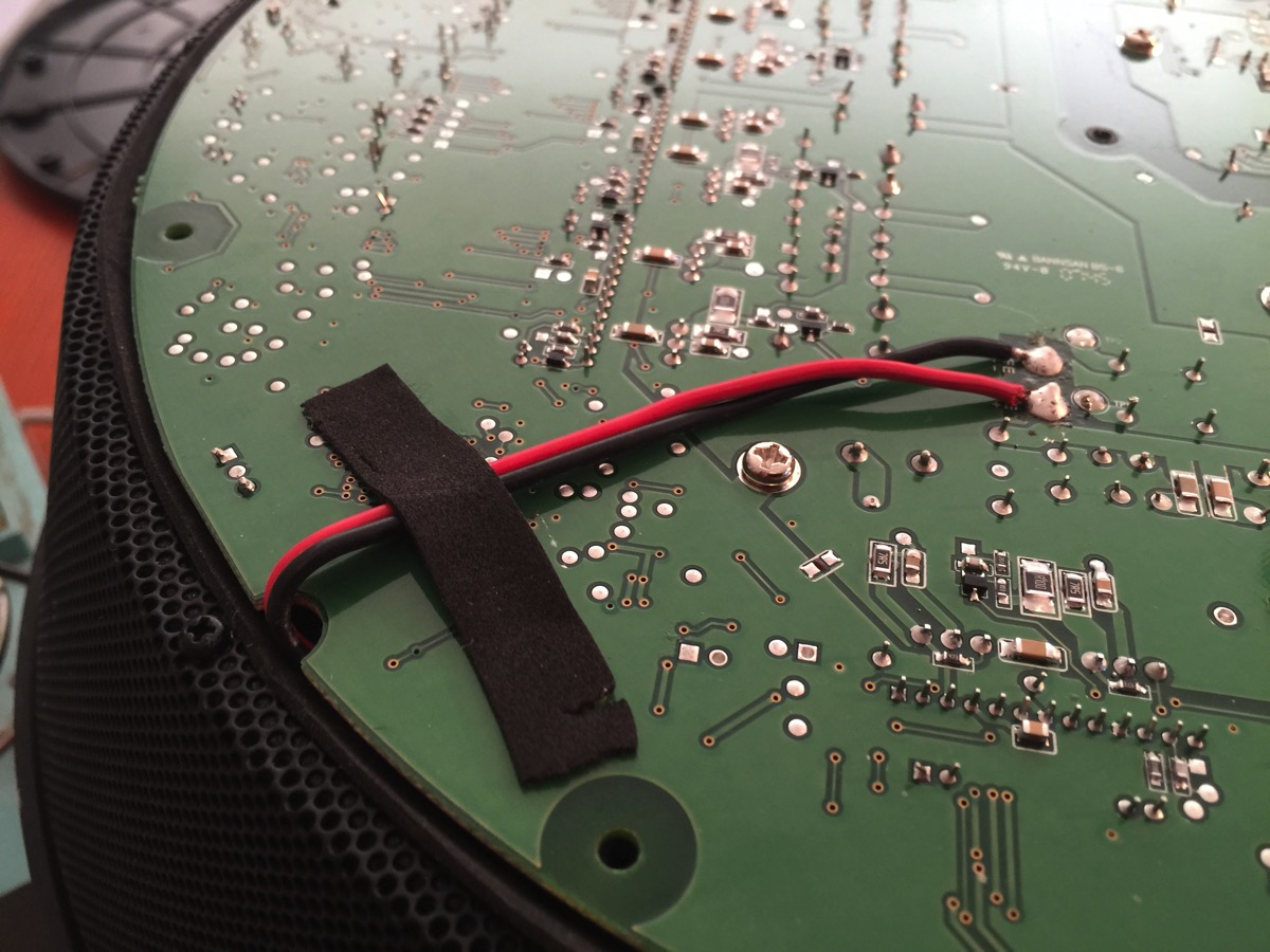
Lift off the bottom. The motherboard is connected to a switch in the upper case, in the picture that is in the upper right. To the left you see that it is held down by the red and black speaker cable. That’s the one we’ll remove so we’ll be able to turn the motherboard over. Heat the two pads with a soldering iron and remove the speaker cable.
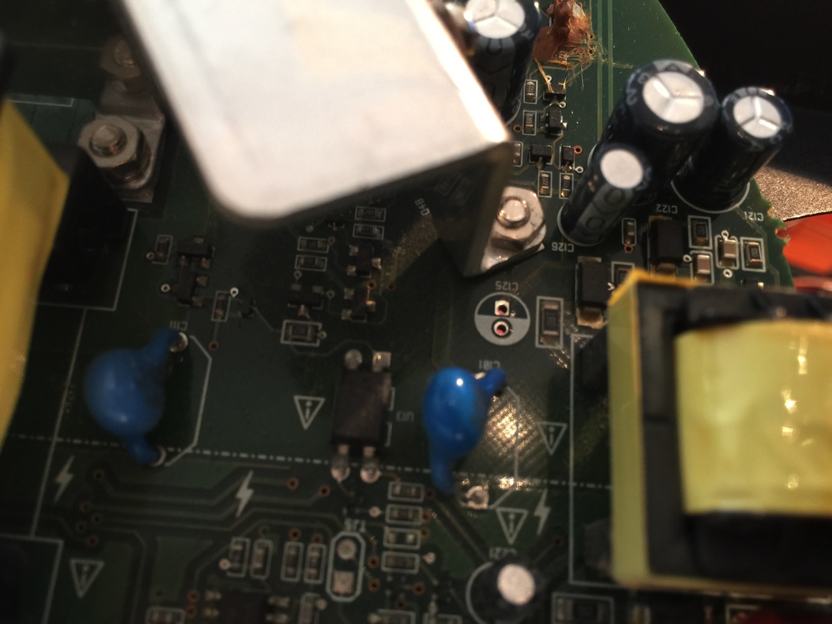
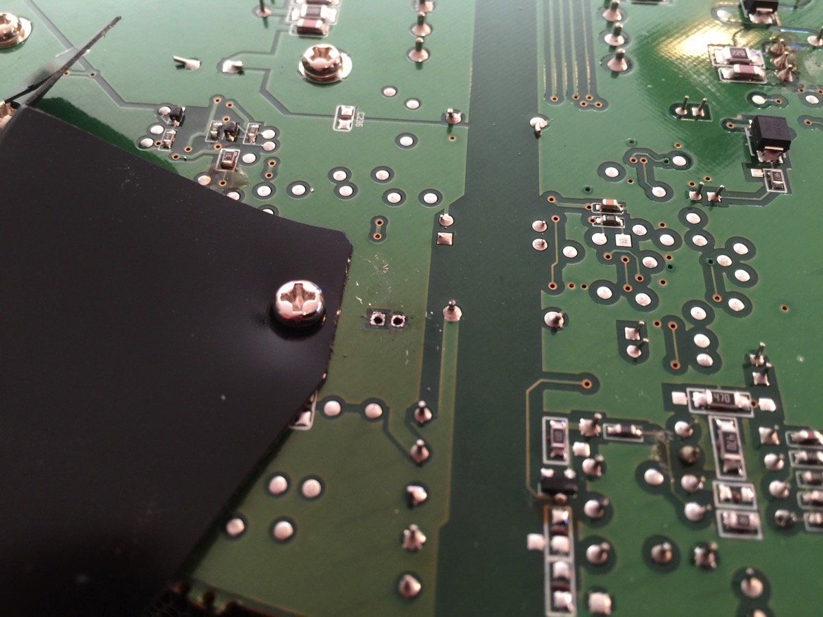
Turn the motherboard over. You can do that even with the power supply cables to the power switch in place. The electrolyte capacitor we’re looking for is marked “C125” and is the one with the red circle in my photo below. It’s a 47µF/25V capacitor. The negative lead is the one marked with dashes and is on the side away from the heatsink, i.e. pointing downwards in my photo.

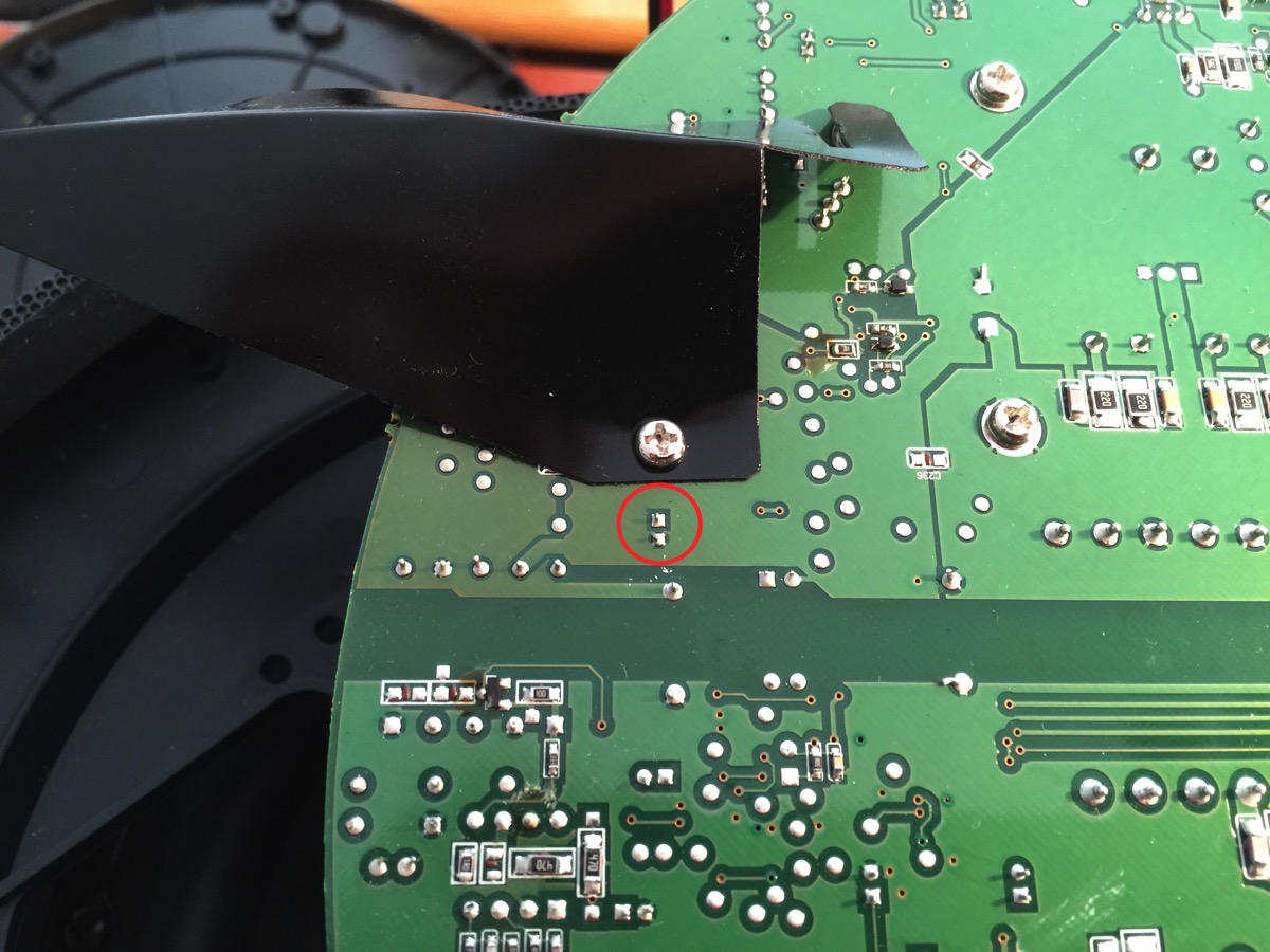
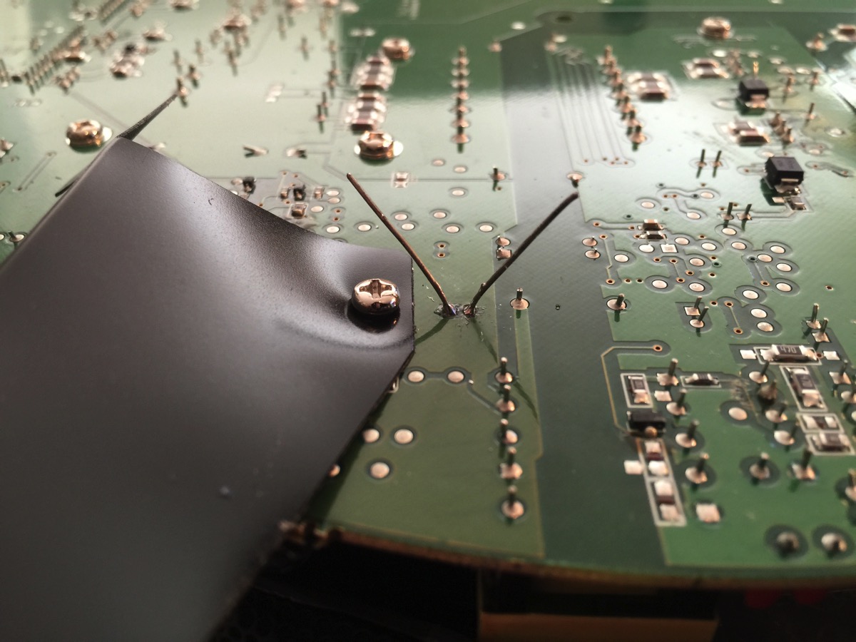
Turn the board over again (without twisting the power cables too much), loosen the screw holding the plastic shield in place, and twist the shield away about 90 degrees, since the C125 solder points are otherwise hidden by the shield. I’ve circled the C125 solder pads in the picture below.
With a lot of patience, heat, solder suction, and solder wick, remove the old capacitor and clean out the solder holes. (Yes, I realize this isn’t always easy, especially since one of the pads is the ground plane and needs more than a little heat, but I can’t teach you to do this in a short few sentences.) Anyway, try not to destroy the circuit board by using too much heat for too long. Use only a suitable regulated soldering iron for this. If you do this right, the end result will look like this from above the board (the negative lead for the capacitor is marked as a filled in white field, downwards in the image). You can see daylight through the holes here.
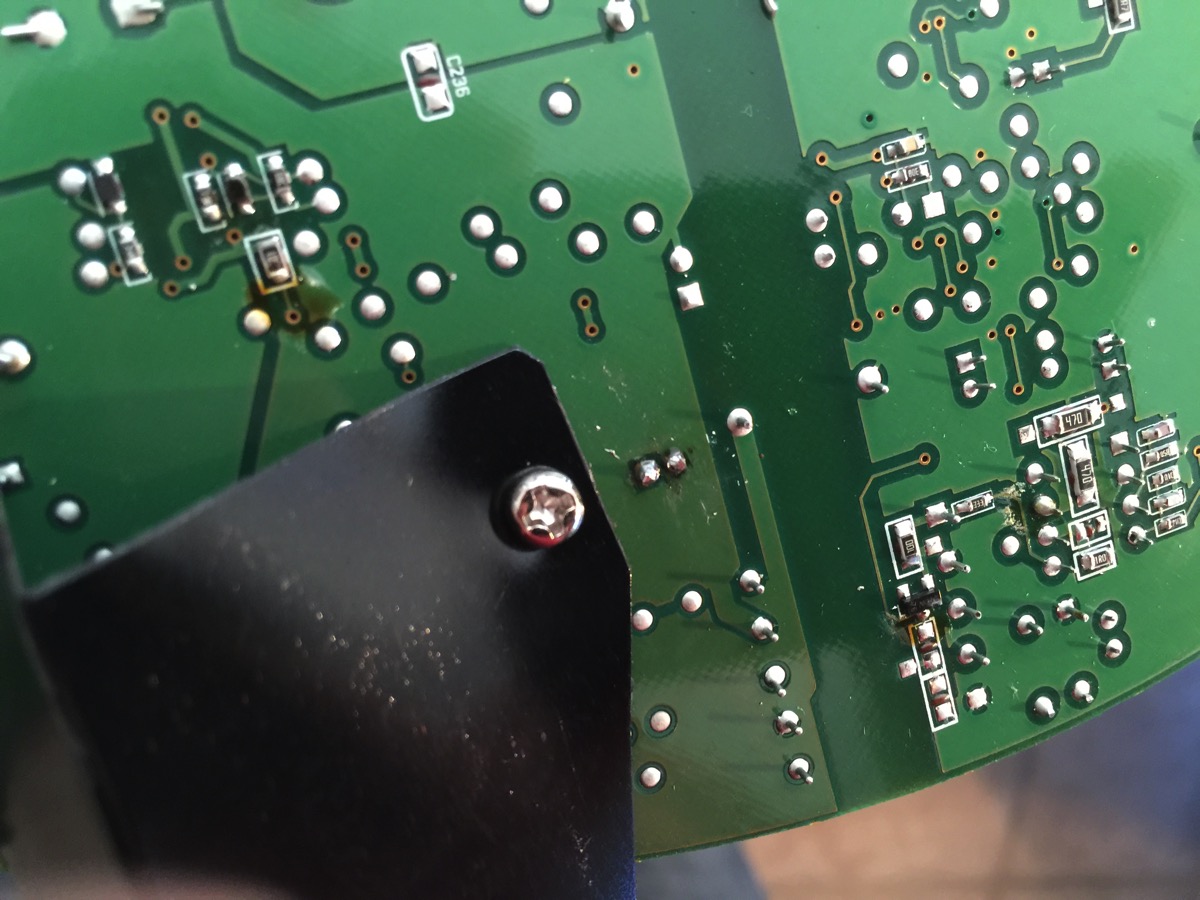
Seen from the solder side:
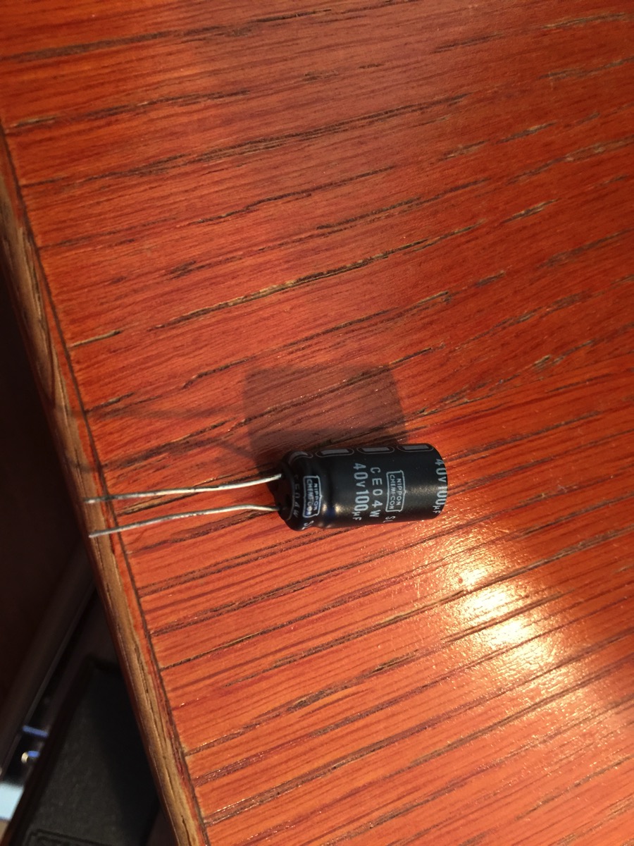
I didn’t have any 47µF capacitors, but I did find a 100µF/40V capacitor in my old stock. It’s very important that the voltage rating is at least as high as the original (25V). I figured that a higher capacitance would be ok, within reasonable limits (turned out it was). If you have to buy a new capacitor, splurge on the absolut best and most expensive you can find. The cheapest cost around 5 cents, while the most expensive can be as much as 15 cents. I’m not kidding. Of course, it may cost you 20 bucks to get it shipped and invoiced, though.
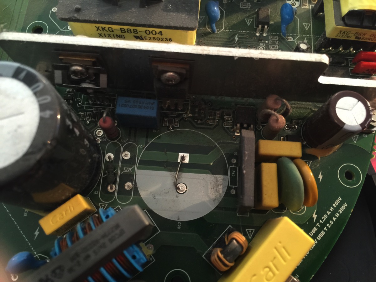
A curious aside: an entire huge capacitor is missing here, replaced by a short. Wonder what the story is behind that.
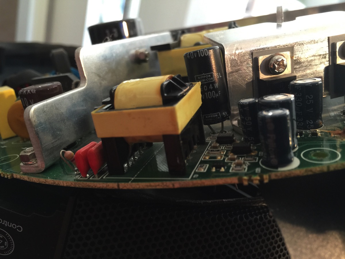
The new capacitor was quite a bit bigger than the old, but that’s not really a problem. Make really, really sure the negative lead is in the right hole, away from the heatsink, i.e. to the left in this image.
Ready to solder on the other side. (When flipping the motherboard around, always check that you don’t twist those power leads too much.)
After soldering and cutting the excess leads, you should have a good connection with no solder bridges. Don’t use too much solder, just barely enough.
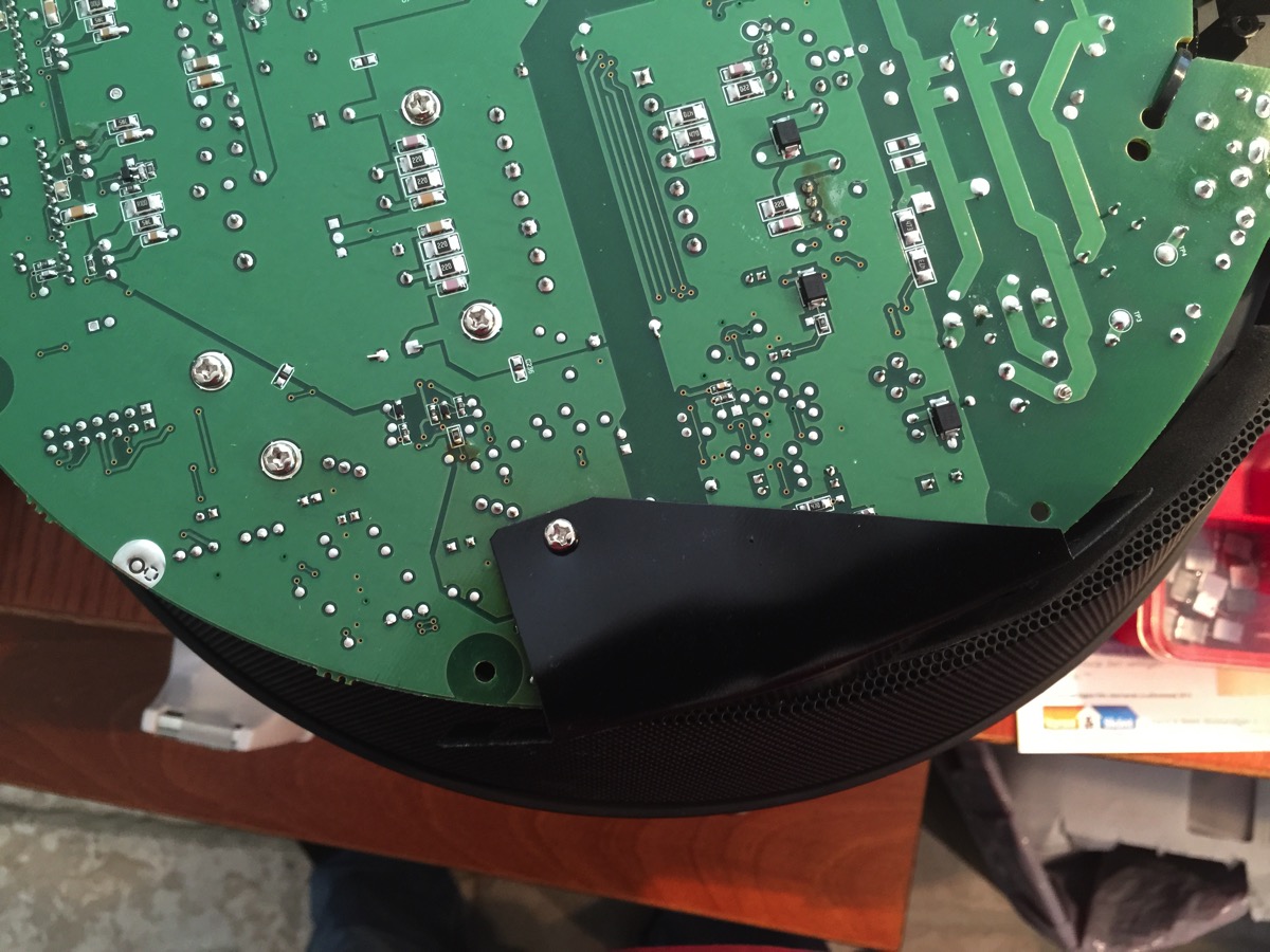
Rotate the plastic shield back into position and tighten the screw holding it in place (there’s a nut on the opposite side of the motherboard that you may need to hold still to do that).
Reattach the speaker leads.
All that remains is to put back the bottom plate and all the screws. There’s a really good chance your system will work fine, now. Mine did, with one exception: when switching on from standby, there’s a single sharp click from the speakers. I’m guessing it’s caused by my capacitor having an excessive value (100µF instead of the original 47µF). We’ll see if this turns out to be a problem or not.