
I have the Razer Mako speakers on my desk. They consist of this heavy, huge amplifier/bass unit and two smaller round treble speakers. It’s a great sounding system, but a lot of them fall victim to the “click of death”. This is a failure mode where the speakers give a regular clicking or popping sound, about once a second, and no other sound comes out of them. As the system warms up, the popping disappears and they function fine again. Until the next time you switch them off and the misery starts over.
With these symptoms, I was pretty sure there must be a failed electrolyte capacitor in the power supply somewhere. The problem is knowing which one. Searching on the net after schematics for the Mako, I found a lengthy and interesting thread about this on the Australian Whirlpool forum (go figure…) where the solution is described very well. Someone, somewhere, figured out which capacitor fails, which makes the repair quite simple.
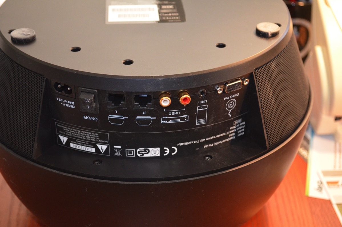
So, here’s what I did, in pictures. Disconnect the base unit from power, satellite speakers and the control pad.

Turn it over. You’ll find 11 (I think) screws in the bottom plate. Remove them all. There’s one in the middle hidden by the label, you have to remember to remove that one, too.
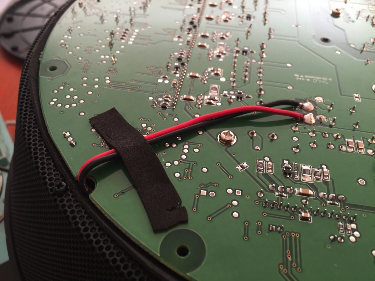
Lift off the bottom. The motherboard is connected to a switch in the upper case, in the picture that is in the upper right. To the left you see that it is held down by the red and black speaker cable. That’s the one we’ll remove so we’ll be able to turn the motherboard over. Heat the two pads with a soldering iron and remove the speaker cable.
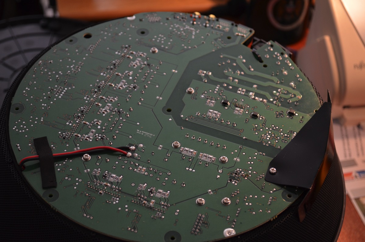
Turn the motherboard over. You can do that even with the power supply cables to the power switch in place. The electrolyte capacitor we’re looking for is marked “C125” and is the one with the red circle in my photo below. It’s a 47µF/25V capacitor. The negative lead is the one marked with dashes and is on the side away from the heatsink, i.e. pointing downwards in my photo.

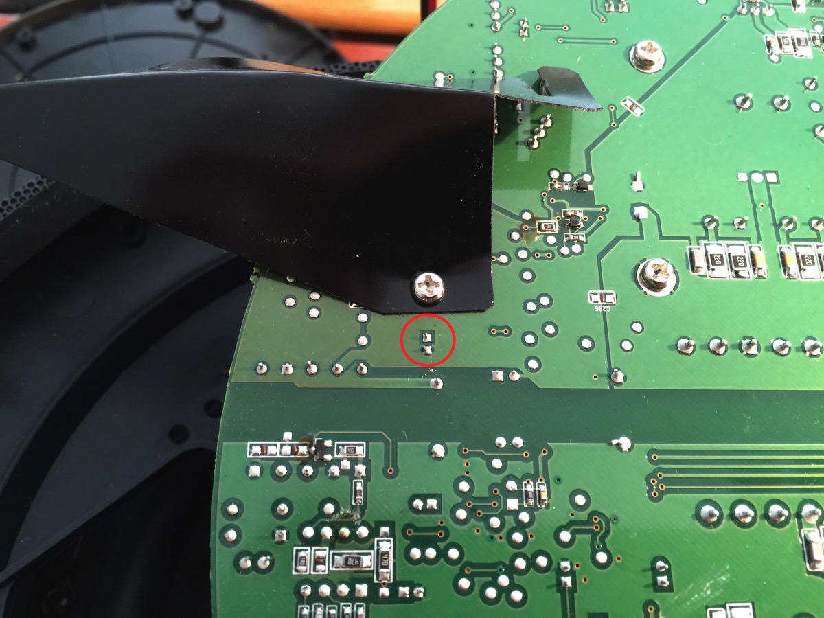
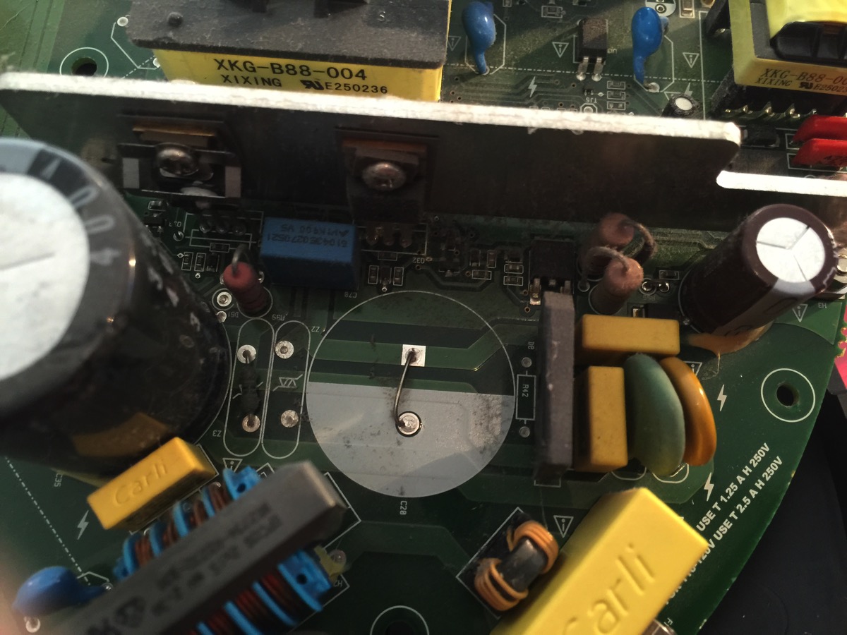
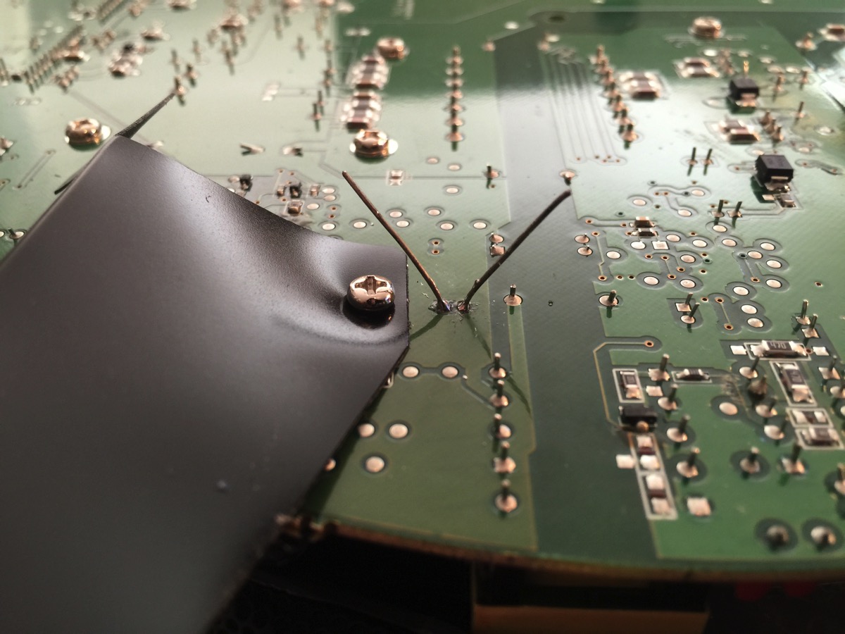
Turn the board over again (without twisting the power cables too much), loosen the screw holding the plastic shield in place, and twist the shield away about 90 degrees, since the C125 solder points are otherwise hidden by the shield. I’ve circled the C125 solder pads in the picture below.
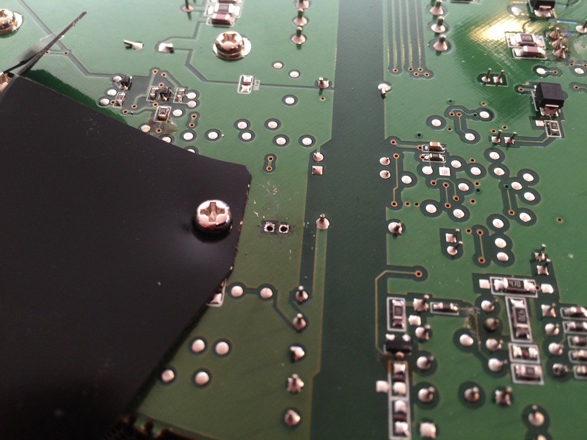
With a lot of patience, heat, solder suction, and solder wick, remove the old capacitor and clean out the solder holes. (Yes, I realize this isn’t always easy, especially since one of the pads is the ground plane and needs more than a little heat, but I can’t teach you to do this in a short few sentences.) Anyway, try not to destroy the circuit board by using too much heat for too long. Use only a suitable regulated soldering iron for this. If you do this right, the end result will look like this from above the board (the negative lead for the capacitor is marked as a filled in white field, downwards in the image). You can see daylight through the holes here.
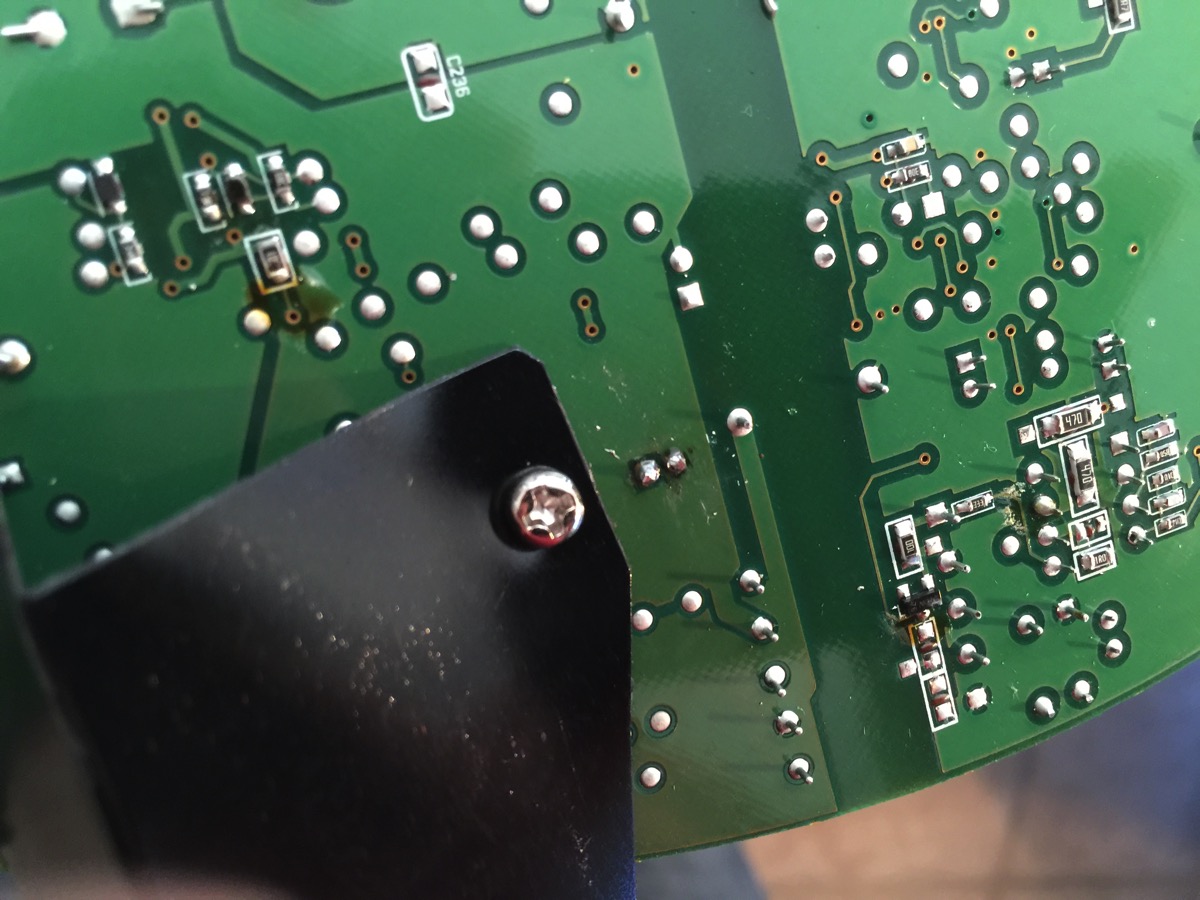
Seen from the solder side:
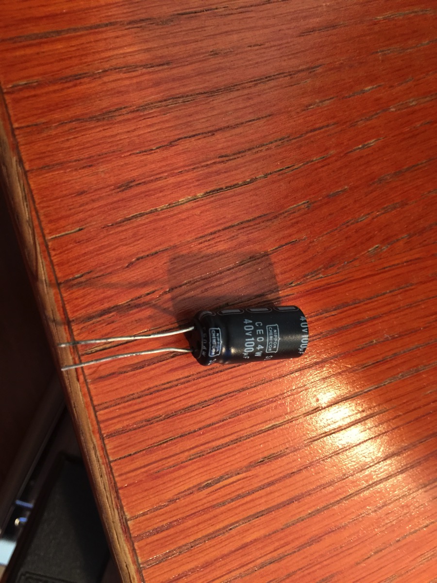
I didn’t have any 47µF capacitors, but I did find a 100µF/40V capacitor in my old stock. It’s very important that the voltage rating is at least as high as the original (25V). I figured that a higher capacitance would be ok, within reasonable limits (turned out it was). If you have to buy a new capacitor, splurge on the absolut best and most expensive you can find. The cheapest cost around 5 cents, while the most expensive can be as much as 15 cents. I’m not kidding. Of course, it may cost you 20 bucks to get it shipped and invoiced, though.
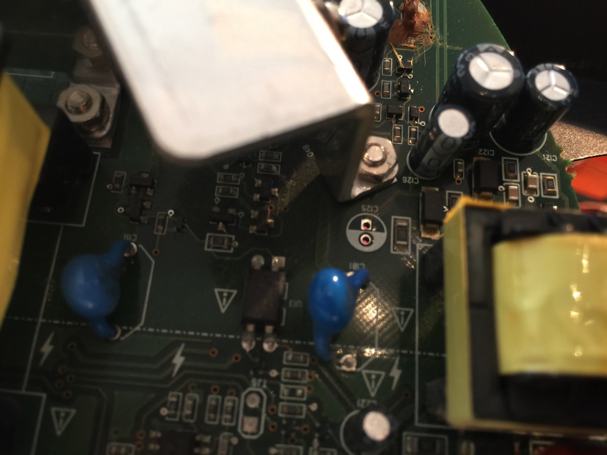
A curious aside: an entire huge capacitor is missing here, replaced by a short. Wonder what the story is behind that.
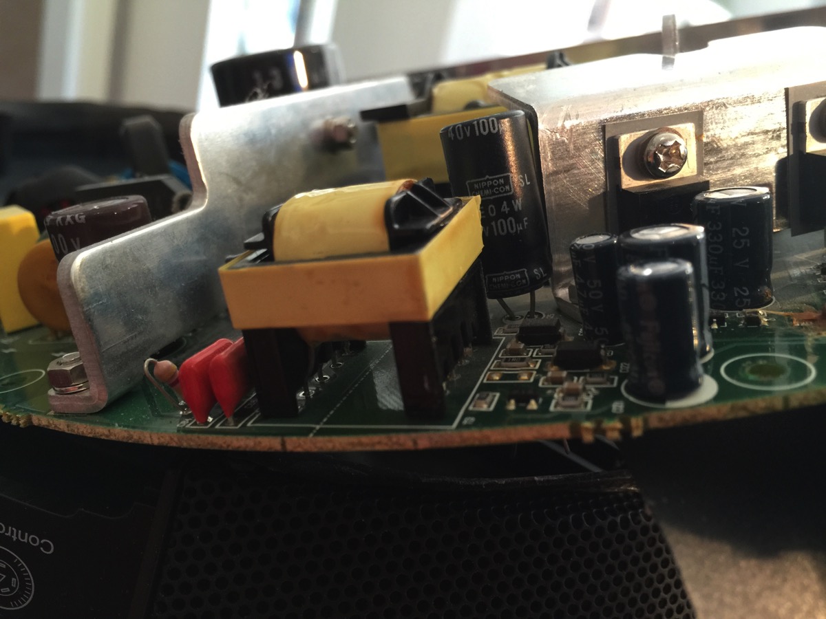
The new capacitor was quite a bit bigger than the old, but that’s not really a problem. Make really, really sure the negative lead is in the right hole, away from the heatsink, i.e. to the left in this image.
Ready to solder on the other side. (When flipping the motherboard around, always check that you don’t twist those power leads too much.)
After soldering and cutting the excess leads, you should have a good connection with no solder bridges. Don’t use too much solder, just barely enough.
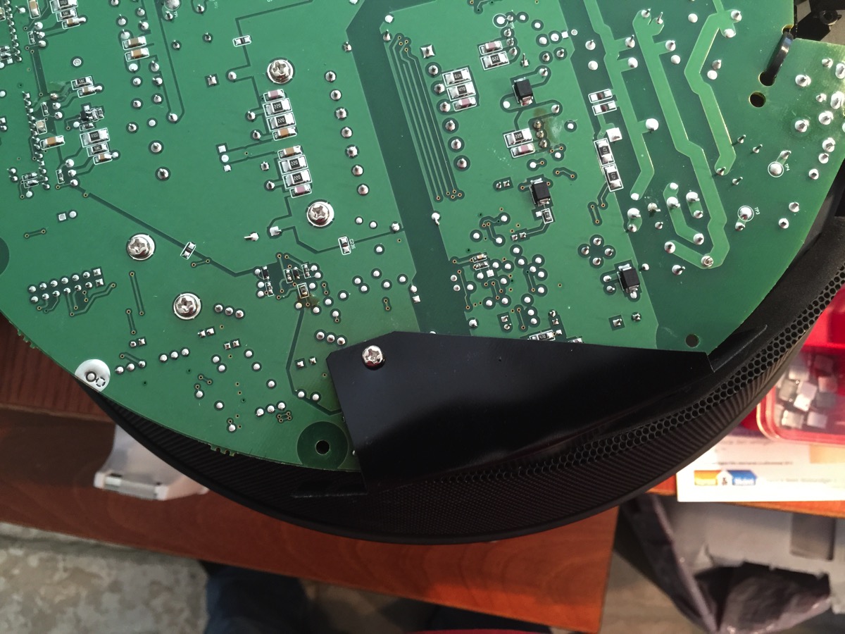
Rotate the plastic shield back into position and tighten the screw holding it in place (there’s a nut on the opposite side of the motherboard that you may need to hold still to do that).
Reattach the speaker leads.
All that remains is to put back the bottom plate and all the screws. There’s a really good chance your system will work fine, now. Mine did, with one exception: when switching on from standby, there’s a single sharp click from the speakers. I’m guessing it’s caused by my capacitor having an excessive value (100µF instead of the original 47µF). We’ll see if this turns out to be a problem or not.
Martin,
Thanks for these instructions!!!!!!! I followed them exactly and my younger sister’s Razor Mako speakers/amp sound incredible. No more click of death!!!!!
I replaced the bad capicator with 47uF 35Watt….. no pops, clicks, nada!!!
thank you, thank you, thank you,
-steve
Hey there,
I’m about to start this process myself and appreciate your thorough and well written instructions.
Quick Q: Which capacitator would you recommend using? Original spec or an upgraded one(which)?
Thanks again.Kristian
Kristian,
I think you should take the next higher voltage rating and the same capacitance. The original is 47µF/25V, and it is clearly underdimensioned (else it wouldn’t fail so easily), so I would choose a 47µF/50V. They’re just slightly larger and should fit with no problem.
Hi, my Razor Mako is completely dead after just starting to make the clicking sound after powering up. Nothing comes on now, any idea what that could be. I did replace the capacitor according to your instructions.
Rickus,
Sorry, no, I can’t answer that. It could be anything. FWIW, my own Mako worked fine for more than two years, but also failed recently in a similar way. No sound whatsoever, but the controller still has lights. I’m trying to troubleshoot it now, but it’s hard. There are no schematics available, and it’s dangerous. The Mako has a switching power supply on the main board, which means that any part of the board can carry mains voltage (and more… some parts I’ve measured up to 380V!) while it’s on, easily electrocuting you. I’m just saying in case you felt the urge to try. Don’t.
I’ll probably get me an isolationtransformer so I can at least do measurements on it while switched on, and lessen the danger a bit. If I by any chance do find out what killed the Mako (before it kills me), I’ll write it up here too, of course.
Thanks for the reply and good luck with the fix….and be safe.
Ok, fixed it. Turns out it was another electrolytic capacitor this time. There’s a new post at: https://www.ursecta.com/2017/12/16/razer-mako-no-click-of-death-fix/
Great thanks, will try the repair tomorrow.
I’m also giving the second fix a go today, my console powers on, and my speakers emit this low tone sound that sounds like an amplifiers feed line that isn’t plugged in, the whole time.
Will post some results if I am successful.
Thanks for this old fix, it already saved my Mako’s two years ago 😀
Cheers
Thank you for this! My Mako started doing this recently and will try it out very soon! I was afraid I’d have to buy new ones.
Perfect! You save my Mako!
big thanks from France
you saved my fu****g Mako
Well damn guys. Mine is making a windup and a pop, Razer customer service was no help. I think Ill try this. I was already looking at new speakers 🙂
Heelo. iwas able to fix the capacitor 47uf 25V on c125. it was working fine but after a while the volume seems to go low and even if i put it to maximum volume it doesnt give off its maximum volume. if i turn it off and back again it seems to regain some volume for a while but again it seems to fade to low volume after some time. Any idea what it could be guys? a low quality capactor maybe or some other issues? thank you
Neel,
My guess would be another bad capacitor. Try running the system for a while, then switch it off and unplug the power cord, then carefully feel if any capacitor is warm. Do be careful with the underside since some of the larger capacitors retain quite a bit of charge and can be dangerous.
dear martin, thank you very much for your assistance. today i sent the board to be checked by a technician. he said that all capacitors were working fine and he suspected that it could be an IQ and nothing could be done. i have no idea what IQ means. but i would like to hear from your opinion. any chances the technician could be wrong about his guess? mako is playing but when it is on max volume it gives only 5/24 of its level vol.
Neelkanth,
First, you’re very specific about the volume (5/24), how did you measure that?
I’m guessing “IQ” means “IC”, that is “integrated circuit”, or as we call it “chip”.
If you sent the technician only the board, there may be a problem. If you connect power to the board without connecting the puck and the speakers, most of the board won’t power up. Most of it will remain switched off, so bad capacitors won’t become warm, and you can’t measure the power supply voltages either. You can’t determine visually if any capacitor is bad, since as far as I know, nobody in this thread saw a bulging capacitor or a leaking capacitor.
This means that unless your technician had his own Razer Mako speakers and puck, he could only check the capacitors one by one by using some form of ESR tool like this one:
https://www.bkprecision.com/products/component-testers/880-dual-display-handheld-100khz-lcr-meter-with-esr.html
If he didn’t have something like that, I doubt he could know if the capacitors were good or not.
If, as he says, an IC would be bad, it would either be the audio processor or the program memory, and then I think you wouldn’t have any sound coming out of the system at all. If a channel amplifier IC would be dead, one speaker would not work at all, while the others would. I can’t think of any one IC going bad that would just reduce the volume.
The problem here is that you can’t really test this system without connecting everything to it. Only then does it switch on all the power supplies. So you probably need to give the entire system to a willing tech to test.
hello martin. you are right about it not being an IC problem, thank you for that. i found out that the problem is with the control pod where a wire must have gone loose,thus giving a low volume to mako. sometimes the full volume is regained for a while then it drops again. music is still enjoyable at its low level, with a groovy subtle bass, but i will definitely have to find out which wire is specifically related to this prob. i will have to be gentle and careful if i am to inspect the control pod since its a critical part of controlling the system.
thank you again
i will drop a word if i find out more about this
stay blessed /|\
Great job, thank you so much. Our Mako works again 🙂
I can’t thank you enough for this post, Martin!
I’m working through this right now, but I have a question about the replacement capacitors that I can use. Mainly, electrolytic vs ceramic. I’m reading that ceramic are better overall so I ordered some for this replacement, but now I’m having second thoughts.
I got these:
https://www.jameco.com/z/TM47-25-Jameco-Valuepro-Tantalum-Capacitor-47uF-25-VDC-10-Radial-Through-Hole_33822.html
Should I stop, and get electrolytic instead?
Thanks in advance!!
Sorry for rushing on the previous comment:
It looks like the capacitors I got were in fact electrolytic, but I was thrown off by the fact that they’re not drum-shaped, like the aluminum ones.
Regardless, is Tantalum a bad substitute for the Aluminum one used for C125?
P.S. My base unit actually has the second huge capacitor that’s missing from yours, so that’s interesting. Now I really want to know the story behind it!
Both tantalum and electrolytic should work if you got the right values. The reason to use electrolytic is price. Tantalum is more expensive.
About the second huge capacitor: what is your mains voltage? 220V or 110V?
That makes sense, thank you. You said to splurge, so I did!
Looks like the voltage printed next to the power switch on my base unit is 110-120V. Since yours is 220V, is my second capacitor meant to compensate for the lower voltage?
Well, it’s logical to use more capacitors on a 110V system, since the current after the rectifier will be twice that of a 220V system (and the voltage will be half). That’s what I thought it was for and your system seems to confirm it. I’m still a bit mystified why it’s shorted out in my system instead of being just left open. But I haven’t tried to analyze that part of the system in depth, so I’ll just leave that as one of life’s mysteries. 🙂
This fixed my Mako speakers nearly four years ago and now it’s clicking again! Hopefully, the same fix will work.
Thank you again for troubleshooting this!
Jed,
Also check out the follow-up post:
https://www.ursecta.com/2017/12/16/razer-mako-no-click-of-death-fix/
Thanks for the info on the click of death! Replaced that capacitor and still have the the Click! It was worth a try!….going right in the trash!, Razer should be ashamed of these things, worked great for a year or maybe 2, then sat in the storeroom for 10+ years….i figured it had to be something simple, right? guess I was wrong
Merci mille fois!
Mon razer fonctionne de nouveau à merveille !
J’ai , comme indiqué, mis un condensateur bien plus costaud.
Seul bémol : la soudure était très très difficile à faire fondre nettoyer.
Merci encore
Thank you so much for your guide! I am so amazed and proud that I was able to fix my speakers with your help. You have saved another pair of speakers from going to waste.
Bonjour,
Il y a quelques années j’avais remplacé le condensateur 125 suite au “click of death”.
Il y a quelques jours, télécommande ok mais plus de son …
J’ai pris la décision de retirer et tester tous les condensateurs (très radical).
Résultat 23 condensateurs possiblement défectueux.
Suite au remplacement des 54 condensateurs électro-chimique tout est rentré dans l’ordre et même plus de clac à l’allumage 😉
https://imgur.com/a/mfwUlst
Hello,
A few years ago I replaced the 125 capacitor following the “click of death”. A few days ago, remote control ok but no more sound… I made the decision to remove and test all the capacitors (very radical). Result 23 possibly defective capacitors. Following the replacement of the 54 electro-chemical capacitors everything is back to normal and even no more clicking when switching on 😉
Nice job!
Thanks to this community… I was able to resurrect my friend’s speaker set after I fixed mine previously.
Thank you all for keeping this alive.
Thanks to this tutorial, I was able to resurrect a speaker set that I just bought it locally for only $40. I already had the capacitors.
Not to long ago I was able to fix my friend’s speaker set, I replaced the capacitor, to my surprise… The speaker set was already been fixed by the previous owner… It had a pretty sloppy job, but was fine for a while, so I replaced once again after 2 years of service and was working fine until a while ago… Now the control pod is flickering and no sound at all, definitely it’s something as from what it was last time.
I couldn’t fix it but we fou6a local one for sale, only $40.
I will eventually try to replace the other capacitor if I get a chance, I really do not want to see it going away to waste.
I’ll keep you posted!
Yes, please keep us updated!
Hello dear community!
It is my 3rd Mako Razer speaker set trying to bring it back to life, this last one gives more trouble than the previous ones.
After replacing capacitors C122 and C125, I was able to get it powered up, control pod works fine, seems like I’m able to turn it on, but I barely hear any sound only if I turn it up at max volume, so… I am getting some sound, but it’s sooo low, I need to bring one of the speakers to my ear to hear it.
I am wondering if anyone has any suggestion on which capacitor should I replace next, thank you kindly for keeping up this small but enthuast community!
*later today…
With the help of my second Mako Razer Speaker set, I was able to determine that I have a faulty control pod…
The set that I just replaced the capacitors works fine with my own control pod, I switched them back and forth.
I have two working sets with two control pods, only one control pod is working, the other one is broken, I took it apart but I doubt is there anything I can do to fix it.
If anyone has any input, please share that information.
None for sale on eBay either. If anyone has one for sale please let me know, I’ll be happy to buy it.
Cheers to everyone!